I am looking to model a system with a thermal energy and water source as well as electricity that is used by a water treatment system, specifically membrane distillation. Is it possible to include water flows in OEMOF? Do you know if any membrane distillation systems have been modelled in OEMOF before?
Hi @awyon, welcome to the board!
If you want to optmise such a system, solph is very flexible. There are examples looking at integrated water, energy, food, and environment systems (cf. github.com/rl-institut/OWEFE). Actually, I currently prefer modelling also the heat sector using water flows instead of resulting energy flows to be able to explicitly express flow and return temperatures.
Specific examples of membrane distillation I don’t have at hand. Still, if you are able to linearise the problem in a meaningful way, it should be possible to model it. Do you want to give some background?
Hi @pschoen,
I just came across your post, and I’m currently thinking about shifting our energy system model from an energy flow-based approach to a mass flow-based approach.
Before making this transition, I was wondering if there are any comparative studies out there that evaluate these two modeling approaches? Or maybe there’s already a discussion on this forum that I’ve missed?
I’d really appreciate any references, insights, or experiences from others who have explored this topic!
Also, sorry if this is a bit off-topic here—I just felt like this post was somewhat related to my question.
Thanks in advance!
Hi @0815paul
This 1995 paper, from the very depths of early high‑resolution contiguous time systems modeling, does cover your question:
- Groscurth, Helmuth-M, Thomas Bruckner, and Reiner Kümmel (1995). “Modeling of energy-services supply systems”. Energy. 20 (9): 941–958. doi:10.1016/0360-5442(95)00067-Q.
A quote:
It is important in our model to comprehend the distinction between physical flows and knowledge about such flows.
The NEMESS model was later coded in C++ as the deeco framework.
In fact, I don’t think energy, exergy (which I once experimented with), mass‑based, and cashflow formulations are mutually exclusive. As the NEMESS exposé indicates?
HTH, R
Hi @0815paul,
it’s maybe slightly OT, but as I assume that modelling water treatment will profit from the discussion, so:
Honestly, I didn’t do an in-depth literature research on the topic. The examples that I know mostly consider energy flows. There is doi:10.1016/j.enbuild.2015.02.031 that compares different storage formulations. If you are at that level of detail already, it can make sense to also have an explicit return. (I have a proceedings entry in review that will also comment on the topic.) Secondly, if you have multiple temperatures to consider, mass can be easier to handle. For example, if you have a complex heating grid: Mass flows just split up, and assuming that temperatures in a (classical) heating grid are pretty much independent from mass flow, in the end you just multiply a position-dependent constant to have (harder to understand) energy.
The deeco framework considered and set flow (I sometimes refer to this concept as “flo” to reduce confusion) and return temperatures in municipal and household systems. These systems were termed thermal sub‑networks and the algorithm used is described in Morrison (2000) in section §8.6 (p146–150) (numbered 161 on the PDF version).
- Morrison, Robbie (31 July 2000). Optimizing exergy-services supply networks for sustainability — MSc thesis. Dunedin, New Zealand: Physics Department, Otago University. doi:10.5281/zenodo.13360487. CC‑BY‑4.0 license.

The associated code is archived on GitHub (search “deeco”). HTH, R
Thank you for your reply.
I am modelling a system with waste heat from a data centre cooling system as heat source for a membrane distillation unit. Temperatures and their changes are central, so maybe as you say I should base the model on the water flows rather than energy flows. How do you express the temperatures in an OEMOF model?
What are the benefits of using OWEFE rather than OEMOF for a system like this?
1 Like
Honestly, I just gave OWEFE as an example what you can do with omeof. The tool is based on oemof.solph and specialises it for integrated water, energy, food, and environment systems. In fact, if you need something that’s rather special, I’d go for (vanilla) solph and not something that builds on it. (If you want to do something that is adequately covered by a derived application, you can take the specific application.)
One way of working with heat in more detail is to use multiple (constant) temperature levels [arXiv:2012.12664] and mass that is transferred between them as it is heating up or cooling down. Still, I think it was a good idea to first look into the core of the problem you want to model. So, for example what is the temperature-dependence of membrane distillation?
I’m not sure exactly what you mean by temperature dependence, but the waste heat is around 45C, which will be transferred to a seawater feed. The coolant/permeate flow in the distillation module will be around 20C.
Temperature dependence would be something like “at 45 °C, you can get 5 liters per hour, at 50 °C, this increases to 5.5 liters per hour”. (Numbers are totally made up, just to give an idea.) If you want to model something in that spirit, you need to design the model accordingly.
It can be useful to distinguish between intensive and extensive variables. See Wikipedia EN:
Circulation temperatures are intensive, circulating media flow rates are extensive.
Optimization problems lend themselves to the idea that these two classes of variable are independent and that the intensities can be set prior to solution. And they often are, in real life, either due to the presence of operational control or from reservoir effects.
If that independence assumption fails, then these dependencies must be embedded in the optimization problem. With the associated mathematical acrobatics that @pschoen is alluding too. And computational penalties as well and perhaps even intractability.
Okay, I see what you mean! The temperature for the heat source is set at 45°C so I will not need to optimise the temperature, but rather model the water flows that can be produced using the fixed heat flow.
I have been searching through the oemof content online to try and find an example of a heat exchanger but without success. The rest of my model is based on water flows and given in kg/h. How do I include a heat exchanger that models the transfer of heat in this system since the flow rate of both inputs to the heat exchanger remains constant?
The way to model heat exchangers is actually very dependent on the level of detail of the model. Often (e.g. air heat exchanger for heat pumps), it is not modelled at all (but implicitly in the COP). A heat exchanger between different hydraulic circles might also not be needed in the model. Can you sketch the model you want to implement? If so, I might give you some directions.
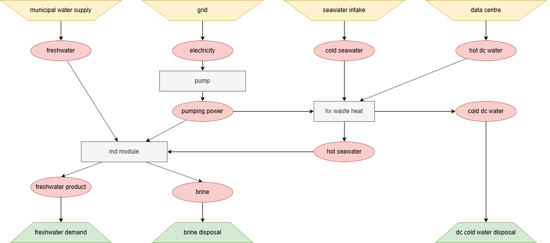
Here is a diagram of what I imagine my system should look like approximately. Any help is highly appreciated.
Thanks a lot. Now I see a bit clearer. So, we know the following:
- flow[(“hot dc water”, “hx waste heat”)] == flow[(“hx waste heat”, “cold dc water”)]
- flow[(“cold seawater”, “hx waste heat”)] == flow[(“hx waste heat”, “hot seawater”)]
- T(“hot dc water”) = 45 °C > T(“hot seawater”) > T(“cold dc water”) > T(“cold seawater”)
What is still to be defined is a proportionality between the two independent flows and the pumping power. You will have to compute this based on your other temperatures and the heat exchanger design. (We do not have a simple predefined helper for that, yet. Of course, you can use TESPy for that kind of calculation, but that’s using the big hammer to drive in a needle.)
Open license needed for diagram
@awyon: I know that this sounds picky but your diagram does not have an open license notice. If you PM me with the author and the year of publication and they agree to a Creative Commons CC‑BY‑4.0 license, I will add that metadata using ExifTool and then replace the file. Alternatively, you can upload that image anywhere suitable on the internet and link back to it — that is acceptable practice. But the status quo is not is unfortunately not tenable and I will need to remove the current PNG in due course under admin rights. Best, R.
PS: Wikipedia is about to delete this recent photograph of mine because the placard shown is protected under copyright and its depiction is substantial. An indication of how important open licensing is for reuse, albeit in another very different context. And we all make mistakes. ![]()
Now resolved with the following embedded metadata:
File Name         : Energysystem-3.drawio.png
Image Description : schematic showing membrane distillation unit and surrounding interconnections
Artist            : awyon
Attribution Name  : awyon
Copyright Notice  : Copyright (c) 2025 awyon
License           : http://creativecommons.org/licenses/by/4.0/
XMP Toolkit       : Image::ExifTool 12.76